
Description
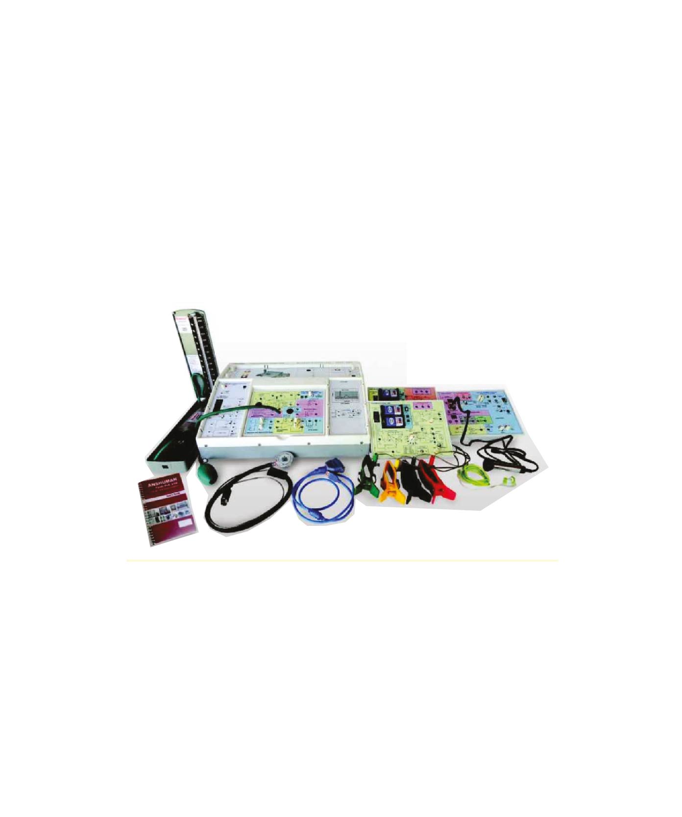
Electromedical Training System
Experiment :
Bio-signal Theory
Arduino Development Environment
GPIO
I-C Communication
UART Communication
Bluetooth Communication
A/D Converter
Theory and Measurement of ICG
Theory and Measurement of EOG
Theory and Measurement of IMG
Theory and Measurement of IEIG
Theory and Measurement of FCG
Theory and Measurement of HIH
Theory and Measurement of NIBP
Theory and Measurement of IT
Theory and Measurement of IR
Theory and Measurement of IR
Theory and Measurement of Respiration
Theory and Measurement of SbC2
Theory and Measurement of Bio-T impedance
Sensor Data Collecting with Raspberry Pi
Web Server Construction with Lightpd
Sensor Monitoring with Javascript
Altam Setting with FTTT
Technical Specification
Display: Min. 10.1-inch Touch LCD, HDMI 1280×800 IPS
Touchscreen
Raspberry Pi 4 CPU: Broadcom BCM2711 1.5GHz Cortex-A72
quad-core
Bluetooth: V6.5.0
Element: 10/100 BaseT
Wi-Fi: 802.11n
Storage: Micro-SD
USB: USB 2.0 Zports, USB 3.0 Zports
HDMI: HDMI 2 * micro-HDMI
Software:
Raspberry pi: Raspthare Nov 2018,
Kermai: 4.14.98-v7+, GCC: 6.3.0
Server: Lighthyd: 1.4.45, PHP: 7.0.33-01-de0bd3
Data Collecting Part:
DAO Module:
MCL: ATMEGA2500
Memory: 256KB Flash
Bootloader: Arduino
Clock Speed: Up to 16MHz
Debug: SWD & USB
External ADC: 4ch
BLUETOOTH Module:
MCL: ATMEGA2500
Memory: 256KB Flash
Bootloader: Arduino
Clock Speed: Up to 16MHz
Debug: SWD & USB
Bluetooth: V2.0, UART 9600bps
ECG Signal Generating Part:
Biological Signal Generator Module:
Display: LCD
Button: SIM
Licence: N/A
ICCR Rate: 800PM
Amplitude: 1mW
Accuracy: +45%
Bio-Signal Measuring Part:
Controller Module:
MCL: ATMENA2560
Memory: 256KB Flash
Bootloader Arduino
Clock Speed: 10 to 16MHz
Debts: SWD & USB
Bluetooth: V2.0, UART 9600bps
Supply Voltage: 3.7v 500mAh Li-Poly Battery
EOG (Electro Outs/Graphy) Module:
Measurement Contents: PVC Conduction
Number of Electrodes: 3 Points
Measurement Range: 10mV ~ 30mV
Filter: Low-pass: 4.5Hz, High-pass: 0.5Hz
Supply Voltage: +5V
PCG (Photo CardioGram) Module:
Measurement Contents: Phonocardiogram
Measurement Sensor: Condenser Mie
Listening Method: Head-Phone
Filter: Low-pass: 100Hz, High-pass: 0.5Hz
Supply Voltage: +5V
EMG (Electro MyoGraphy) Module:
Measurement Contents: Electromyogram
Number of Electrodes: 3 Points
Gain: 10.350x
Differential Input Voltage: 2~5mV
Supply Voltage: +5V
Hill (Human-Human Interface) Module:
Measurement Contents: Human Interface
Number of Electrodes: 2 Points
Output Voltage: 220V, 15mA
Supply Voltage: 1.4Fb/g 3.6V Battery
ECG (Electro CardioGram) Module:
Measurement Contents: Electrocardiography
Measure Point: 3 Points
ADC Resolution: 24HBs
Sample rate (Max): 8kSPS
Input type: Differential, Single-linded
Supply Voltage: 3.3V
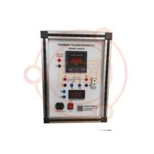
NHP (Non-Invasive Blood Pressure) Module:
Measurement Contents: Blood Pressure
Measurement Controls: Cell wearable
Measurement Range: False Rate: 40~200hpm, Systolic Pressure:
60~250mmHg.
Diastolic Pressure: 40–200mmHg
Supply Voltage: 5V, 12V
BT (Body Temperature) Module:
Measurement Contents: Body Temperature
Measure: Infra-Red Thermometer
Measurement Resolution: 0.02°C
Measure range: -40°C – +123°C
Power supply: 3.3V
SpO2 (Pulse Oximeter) Module:
Measurement Contents: Pulse oximeter
Measure: Optical biosensing
ADC Resolution: 226h
Heat rate monitor:
Power supply: 1.8V, 3.3V
Respiration Module:
Measurement Contents: Respiration
Measurement Point: 3Points
ADC Resolution: 24RBs
Sample rate (data): 8kSPS
Input type: Differential, Single-Haded
Power supply: 5V
Bio-Impedance Module:
Weight-scale measurement
Body composition measurement
Measure Points: 2Points
Measurement Range: 100Ohm – 1KOhm
Accuracy: ±1%
Frequency: Single Frequency(-60Hz)
Power supply: 5V
EEG (Electro Encephalofarm) Module:
Measurement Contents: Electroencephalogram
Number of Electrodes: 3 Points
Band width: 0.1–50Hz
Filter: Hi-pass (0.11Hz), Low-pass (50Hz), Noach (60Hz)
Measurement Range: 0.1–3.3V
Supply Voltage: 5V
Following accessories as standard:
Cable for Signal Measurement
Cuff for NIBP Measurement
Electronode
Headphone
Electronic Seethoscope
Power Cable
User Guide Book II/A
Platform DVD IEA
Machine Holder
Quantity: 2
MATERIAL:
Compressed Wood panels with laminated melamine surface
Dimension(mxmx:n): 2440 X 470 X 750 mm
Top surface around: 16 mm l laminated board 16 mm top visual
with 1mm edging
Color: Black, White, Wooden and ice
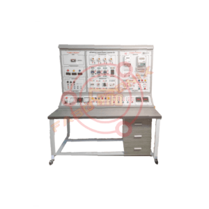
Specification
Operator Control panel:
Components:
Pushbuttons: Min 4 pcs
Min 2 pushbutton with NC contacts
Min 2 pushbutton with NO contacts
Selector switch:
Min 1 pc with 2 contacts
Emergency button: Min 1 pc with NC contacts
Indicator lights: Min 4 pcs (min 1 green and 1 red)
Toggle Switch: min 1 pc
All buttons rated for min 2A – 240 V AC
Power Supply:
24V DC power supply Module:
Input Voltage: 1 ACHO = 220 V (50 Hz)
Output Voltage: 24 V DC
Output current: Min 1 A
3Phase power Supply Module:
3 Phase lights
Input Voltage: 3 phase AC 220 V / min 15 A / 50 Hz
Output Voltage: 3 phase AC 220 V / min 5 A / 50 Hz with circuit breaker
AC inverter drive/ Frequency Converter:
Input: 3 phase 220 V AC, 50 Hz
Output: 3 phase 220 V AC, 0.44 W
Min Frequency Range: 1-500 Hz
Programmable via PLC
3Phase Induction Motor:
Operating Power: 3e AC 220V / 0.18 – 25kW
Speed: min 1350 RPM
V: A Startring
Diagram of motor wiring (Y- Δ) on the front panel
Separately manufactured with a base for educational safety.
separate operator panel with safety socket (preferred)
Programmable Logic Controller Module:
Each trainer board should contain one (01) PLC. The tenderer is
free to choose any PLC from following specification. However,
the mentioned minimum number of each PLC must be provided.
CPU S7-1214C (Minimum 01 set):
75 kByte main memory, 4 MByte program memory.
Interface: RJ45
IJOK:
14 digital inputs (24 V DC)
10 digital outputs (24 V DC, 500mA)
2 analogue inputs, 10 bit (0 – 10 V)
CPU module:
Analogue output SB 1232 AQ
AO 1 x 12 Bit (x 10 V DC/0 – 20 mA)
TTA Portal with STEP 7 Basic v17 or above (Educational and perpetual License)
CPU: XPS4.30MHC-US (Minimum 1 set)
Supply: Voltage: 100-240 VAC
No. of Inputs: 16
No. of Outputs: 14
Input Type: 24 VDC StaticSource
Output Type: .TRelay
Programming software (Educational and perpetual License)
DVP-ES2 Series (Minimum 1 set)
Supply/Input/Output: AC/DC/Relay
MPU points: 16
Program capacity: 16k steps
Built-in with 2 COM ports: 1 RS-232 port and 2 RS-485 ports, all
are able to operate independently (ExtractSites)
Max. I/O points: 256 input points + 16 output points, or 256 output
points + 16 input points
DVP-EX2 MPU is built in with 12-bit 4AD/2DA and offers
analog/temperature modules of 14-bit resolution.
Built-in with 8 high-speed input points (2 points for 10MHz, 6
points for 10KHz) and supports U3D, UI/O DL, ADI counting
modes.
Programming software (Educational and perpetual License)
CPU: S965-132Bit (Minimum 1 set)
Communication Ports: 1 Type B 2.0 Full-Speed USB and 2
Ethernet/IP Ports
Application Memory 2 Megabytes
Module Type: Compact digit Controller
Local I/O modules 16 I/O modules
Communication rate, Ethernet: 10 Mbps / 100 Mbps / 1 Gbps
No. of Ethernet nodes: 40
No. of supported sockets: 32
Programming software (Educational and perpetual License)
Fan
Operating power: DC 24V / 9W
Electric Comacono/SwIndepar Set
(All components must be from reputed brands (e.g: Schneider/ABB/
Siemens or equivalent) and have CE certificate. All ratings must
be appropriate to control offered electro-mechanical machine.)
Fused Fiber Module: Sea
Off-Delay Timer (Stace): 1ea
On-Delay Timer (Stace): 1ea
Main Magnetic Contactor: 2ea
Auxiliary Magnetic Contactor: 1ea
i. Contact: Ia3b
Relay Module: 6ea
ii. 8-ph relay: 2ea
iii. 11-ph relay: 2e
iii. 14-ph relay: 2e
Electronic Over Current Relay (EOCR): 2ea
i. Time-satting: 0–30sec
Counter: Tea
Terminal Block: 1ea
i. Structure: 2-stage 20P
Terminal Block: 1ea
i. Structure: 1-stage 19P
Temperature relay: 1EA
i. Input: Thermocouple CA (K) Thermal Resistance Pt (100Ω).
ii. Control output: relay output
13) D.I. Thermal Overload Relay: 1ea
14) Soft starter: 1ea
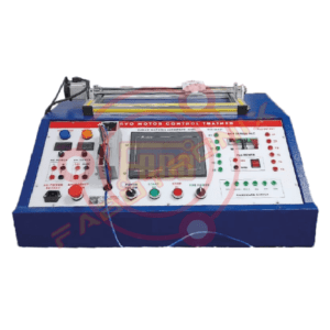
Motors
Three Phase Induction Motor: 2 sets,
Operating Power: 3p AC 220V / 0.175 – 25kW
Speed: 1m 1350 RFM
A. Starting
Diagram of motor wiring (Y-A) on the front panel
Separately manufactured with a base for educational safety.
Separate operator panel with safety socket (preferred)
Workstation
Aluminium/Skel Profile Frame for Module Stacked Storage:
Rigid workstation
Two-sided structure is preferred
Simulation Software
The Controls Simulation Software features true simulations of the
components of the offered electrical trader.
The precise simulations allow students to complete all the exercises
in the training system courseware on a computer without the
need for any actual equipment.
Basic Practice Part
Explain the function, type and principle of operation
Training materials necessary for parts training are provided by
step-by-step method
Provide learning window function to provide electric parts and
actual circuit diagram with explanation in 3D form
Circuit Wiring Part
Describe the composition and operation principle of the basic
circuit of electric wiring
Training materials necessary for parts training are provided by
step-by-step method
Electrical circuit diagram, internal wiring diagram and component
cross section diagram
Providing follow-up exercises through distribution boards with
explanations of circuits
Exercise Part
Provide training drawings
Provide the following formula exercises along with the description
of the circuit configuration
The same parts are composed in 3D form for the same effect as the
parts are configured on the actual distribution board
The circuit training part and the drawing part are provided at the
same time so that you can practice while checking the drawing.
All parts’ settings are provided by the user’s direct input by analog
method, not by digital input method.
Exercise Practice Circuit
Motor control circuit
Conveyor control circuit
Lift automatic control circuit
Motor time limit control circuit
Factory power wiring
Water supply equipment control circuit
Free Wiring Fair
Virtual mode-dimensional space of the working space is provided,
and 560 ° screen can be rotated in any direction up, down, left and
right, so it can be easily checked in any direction up, down, left and right of the part.
A total of 60 parts are provided in the same form as the real one in
3D form, and single and three phase parts are used separately.
Basic R, S, and T terminals are provided on the power distribution
training board, and the user can use single and three phases according
to their needs through wiring as needed.
Wires are available in six colors, red, blue, black, yellow, green,
and white, allowing users to select and wire them according to
their purpose.
Connection Cables
The components modified for educational use should have 4mm
banana sockets for connection.
Color: Green, Yellow, Red, Blue
Qty: 5 Sets for each length and each color
Length: 30 cm, 60 cm, 90 cm
Manuals
Instructor’s Manual: 1 set
User Guide: 1 set
Language: English
Machine Holder
Quantity: 2
MATERIAL: Compressed Wood panels with laminated melamine
surface
Dimension(maximum): 2400 X 470 X 750 mm
Top surface around: 12 mm laminated wood board 16 mm top
visual with 1mm edging
Color: Black, White, Wooden and Red
Surface Solid: be scratch proof
Base: Cold rolled Mild Steel tubular frame or Made with
heavy-duty mild steel
PVC leg stopper for floor protection
Paint: Mild steel part protected with powder coating bent paint
PVC edge banded with his moth plate to protect moisture pelting
Photopixel and Oven baked powder foam finish for anti-mist and
longevity
Anti-mascus chemicals added to make the board termite-proof
Accessories:
Single-phase power cord
4mm Banana Socket-1Set
User Manual
Others:
Brand: FaboTronix
Country of Origin: China, taiwan, japan.
Manufacturing: Assemble in Bangladesh
Training

Reviews
There are no reviews yet.