

Description
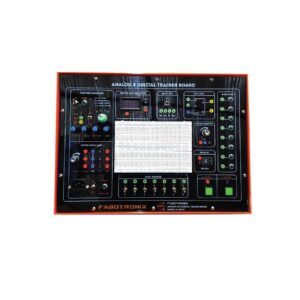
Advance Smart Trainer Plat form with built in Software
Technical Specification :
1. Platform (Advanced)
Embedded OS-based smart learning platform : Intel® CPU Atom™
Processor: 16GHz, 800MHz FSB, 512KH 32 cache;
2.1W ultra-low-power system, PCI6x2 package:
Hyper- threading and 45nm technology ;
Ethernet, USB and Serial interface :
Touch screen resolution: 800 x 480 ;
124-point connector to connect an experimental module :
Integrated measurement board employing the 3-core CPU ;
Installed measurement application software (OS: Microsoft Embedded) ;
Multilingual selection and smart touch user interface control ;
Audio and video control functions
Signal input (2-channel)
Oscilloscope:
Impedance: Min. 1MΩ/ 20pF;
Max voltage: 50V/p.p;
Bandwidth: Min. 4MHz;
Sample rate: 40MS sec./ACC resolution: >10bit;
Voltage DIV: 0.105/20/1.6/30.20.1/50mV/200Hz;
Time DIV: >22 times 1us=10s;
Trigger: Auto, Single, Stop Mode;
Memory: Streaming to host
2) Voltmerie & Ampere meter
Measurement: AC/DC voltage, current, power (VA);
Function: Mean value, Peak value, Peak-to-Peak value, Root
mean square (RMS) value; Range: Auto & Manual Mode (>
Stap 100mV=30V)
3. Signal output (-channel)
Function / Pulse / Arbitrary Generator
Impedance: Min. 300/2200mA; Amplitude: 200mVpp, 2Vpp,
20Vpp (Max. 20Vpp); Frequency: 0.11Hz – 1MHz; Range:
0.11Hz/11Hz/10Hz/100Hz/1MHz/10MHz/100kHz
(7-step); Output waveform: Sine, Square, Triangle, Logic, DC
Pos (+), DC Neg (-)
DC Source
Range: 100mV, 1W, 10V; Voltage Source: 0 ~ 10V
Digital input (digital analyzer/control)
Number of channels: 16 (Int. +Exit);
Input voltage: TTL/CMOS; Max. voltage: 20V;
Frequency: 100kHz; Process mode: Low, high, DC;
Memory: Streaming to host;
Function: BIN (24-bit), OCT (8-bit),
DEC (10-bit), HEX (16-bit)
Digital input (Signal generator)/input
Number of channels: 16 (Int. +Exit);
Output voltage: TTL/CMOS;
Output current: 2msI; Max. voltage: ±15V;
Output frequency: 100kHz;
Memory: Streaming to host; Function: BIN (24-bit),
OCT (8-bit), DEC (10-bit), HEX (16-bit)
Relay output
8-relay COM, NONC (Normally OpenClosed); 2AVDC / 1A
Variable power supply
3-channel DC power
VI voltage: DC 0 ~ ± 20V 1A; V2 voltage: DC 0 ~ ± 20V 1A; V3
voltage: DC 0 ~ ± 20V 1A
3-phase AC power
AC voltage: AC 14Vrms 1A (Resolution: 0.1V);
Frequency: 11Hz ~ 150Hz (Resolution: 1Hz)
Advanced 3-phase power
Function: Sine, V-Sine, Block, Pulse;
VI voltage: AC 0 ~ 100%; V2 voltage: AC 0 ~ 100%;
V3 voltage: AC 0 ~ 100%; V2, V3 phase shift: 0 ~ 359°;
Frequency: 1 ~ 150Hz; Close frequency: 10kHz ~ 32kHz
Digital Multimode
Voltage: DC 1V, 10V, 100V,
AUTO AC 700mV, 7V, 70Vrms, AUTO, 401k ~ 20kHz;
Current: DC, 20kHz, 2A, AUTO; AC 500mA, 2Arms, AUTO,
401k ~ 2kHz;
Resistance: 100Ω, 1kΩ, 10kΩ, 100kΩ, 1MΩ, 10mΩ, AUTO;
Capacitance: 10πF, 100πF, 1μF, 10μF, 100μF, 100μF, AUTO;
Continuity diode: 1V, 10V
Fixed power supply
Fixed voltage: +3.3V/2A, +3V/2A, +13V/500mA (Common)
Application software for measurement (modelled in the main unit)
Measurement control
All functions are directly connected to the equipment to control
and to set up I/O values identical to actual instrumentation devices.
Overlineover: By setting the signal (Voltage) value according to
the time setting (22 values between 1us and 10s per time unit), you
can display a waveform graph for each of the two channels.
Channel A (yellow) and Channel B (blue), and compare
waveforms. It provides XY (Lissajour figure) and trigger functions.
Power meter:
Calculation of wattage (voltage x current) is possible through the
voltage input to channel A and current of channel B.
Voltage & Amplifier meter: You can select a measurement mode to
measure voltage or current in two channels, and can measure
current through a virtual resistance input.
There are five measurement modes: AV, JAVJ, P, PP, and RMS.
Function generator:
It provides the function of selecting basic output signals
[sine/square/ triangle /logic/DC (1)/DC (v)].
The user can configure a setting display window showing the
setting status and the voltage output level and frequency
Pulse generator:
The setting display window, voltage output level and frequency
can be configured. It provide the function of controlling and
adjusting the pulse output signal (input-level bipolar/substrate
pulse) and pulse width.
Arbitrary waveform generator:
It provide basic waveforms such as sine wave, triangle wave, and
square wave provided by the function generator.
It also offer various types of other waveforms suitable for laboratory
experiments (All Sine, Half Sine, SinDX/XX, Cosine,
Tangent, Up Rump, Down Rump, Up Stair, Down Stair, and Noise).
DC source:
DC voltage generated in the range from -10V to +10V. The range
selection helps increase accuracy at the time of setting up the voltage.
Digital multilinear:
The user can select a range for measuring DCV (DC voltage),
ACV (AC voltage), DCI (DC current), ACI (AC current),
short-circuit resistance (licey), resistance, capacitance, diode measurement.
3-channel DC power supply:
each channel of V1, V2 and V3 makes an output of DC voltage
from -20V to 0V to +20V. (In case of short circuit in the output
terminal or overload in the circuit of a particular experiment, the
alarm goes off and the output of the power supply will be out of the circuit protection.)
3-phase AC power:
The output voltage and output frequencies of V1, V2, and V3
output terminals are simultaneously varied. The accuracy of the
output voltage is 0.1V, and the outputs of V1, V2, and V3 can be
used for the V/A – type AC power circuit.
Advanced 3-phase AC power:
The 3-phase AC power (V1 – V3) can be adjusted as a percentage,
and make a variable output. The phase shift of V2 and V3 is 0.5 –
339°, the clock frequency is 10 – 32kHz, and the frequency is 1 –
150Hz. It provides an arbitrary setting output function and an
output waveform display function.
Digital input:
The digital input data are displayed up to 16 bits on the touch
screen and can be switched to four types of mirrors system (2/8/10/16).
Digital output:
The digital output data are displayed up to 16 bits on the touch
screen and can be switched to four types of numeral system (2/8/10/16).
Relay:
Eight relays can be individually controlled, and the status of N-C
(Normally Closed and N-O (normally Open) are displayed.)
2) E-book function
Format HTML:
The composition is the same as the experimental manual. The
electronic circuit practice consists of 16 chapters whereas the
electric circuit practice consists of 11 chapters.
It enables quick selection and movement of the practice tasks as
well as table of contents for each section.
Flash design for circuit connection enables learning in more details.
The circuit diagram of experimental modules can be enlarged or
reduced in the HTML document by scribling the mouse.
11) Circuit design and simulation software (Should be installed in the main unit)
6-language design (built-in compiler): Real-time control and
measurement. Circuit design and simulation applications.
Power electronic circuits, electronic circuits, Power source or
signal source design, Power system, Mechanical load, Renewable
energy circuits, Electrical drive circuits; Digital logic circuits,
Control circuits, Electrical system, Mechatronics system
Machine Holder
Quantity: 2
MATLAB/M.: Compressed Wood panels with laminated
melamine surface
Dimension(maxmax)): 2440 X 470 X 750 mm
Top surface around: 16 mm Laminated board 16 mm top visual
with 1mm edging
Color: Black, White, Wooden and etc
Surface skill be scratch proof
Base: Cold rolled Mild Steel tubular frame or Made with
heavy-duty mild steel PVC leg stopper for floor protection
Paint: Mild steel pan protected with powder coating heat paint
PVC edge banded with hot metal glue to protect moisture gaining
Phosphatized and oven baked powder paint finish for anti-tests
and longevity
Anti-tasects chemicals added to make the board termite-proof
Accessories:
Single-phase power cord
4mm Banana Socket-1Set
User Manual
Others:
Brand: FaboTronix
Country of Origin: China, taiwan, japan.
Manufacturing: Assemble in Bangladesh
Training

Reviews
There are no reviews yet.