Description
Specification:
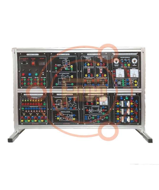
Module One
Basic Electronic Circuits
Diode and Transistor Switches
Basic applications of Operation Amplifiers (I)
Experiment 4: Inverter OP Amplifier fin 1 kHz and 2 VPP
Experiment 5: Inverter fin 1 kHz and 2 VPP
Experiment 6: Non-Inverter OP Amplifier fin 1 kHz and 2 VPP
Experiment 7: Voltage Follower fin 1 kHz and 2 VPP
Basic Applications of Operation Amplifiers (II)
Experiment 8: Comparator Vs ±12 V,V ref ±1 V
Experiment 9: Zero Crossing Detector Vs ±12 V , V ref 0 V
Experiment 10: Photoelectric Controller Vs ±12 V , V ref 6 V
Module Two Waveform Generator Circuits
Schmitt Trigger Circuit
Experiment 1: Schmitt Trigger Vs ±12 V , fin 1 kHz, Vin and 10 VPP
Experiment 2: 555 Delay Circuit Vs 12 V , TON 6 secs
Experiment 3: Delay Turn off Circuit VCC 12 V ,TON 4 ~ 9 secs
Astable Multivibrator
Experiment 4: OPA Astable Multivibrator Vs ±12 V , V out 22 VPP Square wave
Experiment 5: 555 Astable Multivibrator VCC 12 V , V out 11 VPP Square wave
Experiment 6: Sparkling Lamp
Crystal Oscillator
Experiment 7: TTL Crystal Oscillator for 100 kHz ~ 4 MHz
Experiment 8: OPA Crystal Oscillator for 1 MHz, V out and 6 VPP
Module Three
Digital Circuits
BCD Adder
Experiment 1: BCD Adder IC 4560B
BCD Subtractor
Experiment 2: BCD Subtractor IC 4560B
Applications of Timer
Experiment 3: Monostable Circuit VCC 12 V , TON 5 ~ 10 secs dot
Experiment 4: Touch Switch VCC 12 V , TON 5 secs
Experiment 5: Alarm Circuit VCC 5 V , IC LM555, Speaker
Digital Display Circuit
Experiment 6: 4518 Counter
Experiment 7: Digit Display Circuit VCC 5 V, IC CD4518
Application of LCD
Experiment 8: LCDM Circuit VCC 5 V, IC: 4511
Module Four
Signal Process Circuits
Digital to Analog Converter
Experiment 1: R 2R Ladder Network Circuit VCC 8 V, V out= 0 ~ 7.5 V
Experiment 2: D byA Converter VCC ±15 V, IC DAC0800
Analog to Digital Converter
Experiment 3: A/D Converter VCC 5 V, IC ADC0804
Filters
Experiment 4: Low pass Filter VCC ±15 V, fin 100 Hz ~ 5 kHz and 4 VPP
Experiment 5: High pass Filter VCC ±15 V, fin 100 Hz ~ 5 kHz and 4 VPP
Experiment 6: Bandpass Filter VCC ± 15 V , fin 50 Hz ~ 280 Hz and 4 VPP
Experiment 7: Bandstop Filter VCC ± 15 V, fin 50 Hz ~ 280 Hz and 4 VPP
Module Five
Regulated DC Power Supply
Applications of 7800 Series Regulator
Experiment 1: 7805 Regulator Characteristic Vin 8 ~15 V, V out =5 V
Experiment 2: 7805 Expanded Voltage Vin 12 V,V out =5 ~ 7 V
Experiment 3: 7805 Variable Regulator Vin 12 V, V out =11 V
Experiment 4: 7805 Current Source RL 0 ~330Ω, I out= 10 mA
Applications of 7900 Series Regulator
Experiment 5: 7905 Regulator Characteristic Vin 8 ~15 V, Vout =-5 V
Experiment 6: 7905 Expanded Voltage Vin 12 V, V out = -5 ~ -7 V
Experiment 7 7905 Variable Regulator Vin 12 V, V out = -11 V
Experiment 8 7905 Current Source RL 0 ~330Ω, I out =11 mA
Function Generator and DC Power Supply
Waveforms: Sine, Triangle, Square and TTL Pulse
Amplitude: 10Vpp
Impedance: 50Ω ±10 %
Duty Control: 30 % to 60%
Display: 6 Digit LED
Frequency Range: 10Hz to 100 kHz 4 Ranges
Frequency Range: 100Hz to 1 MHz 4 Ranges
Constant Voltage Output: ± 5V,±12V
Variable Voltage Output: 0 V to ±15V
Power source 220 to 230V AC 50Hz 1 Phase
Accessories:
User Manual: 1 Nos
With Standard Accessories.
4mm Safety Socket
Others:
Brand: FaboTronix
Country of Origin: China
Manufacturing: Assemble in Bangladesh
Warranty: 01(One) Year

Reviews
There are no reviews yet.