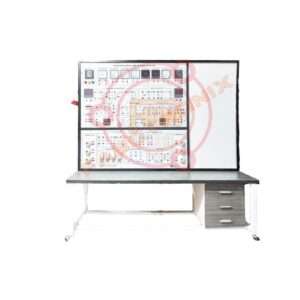
Description
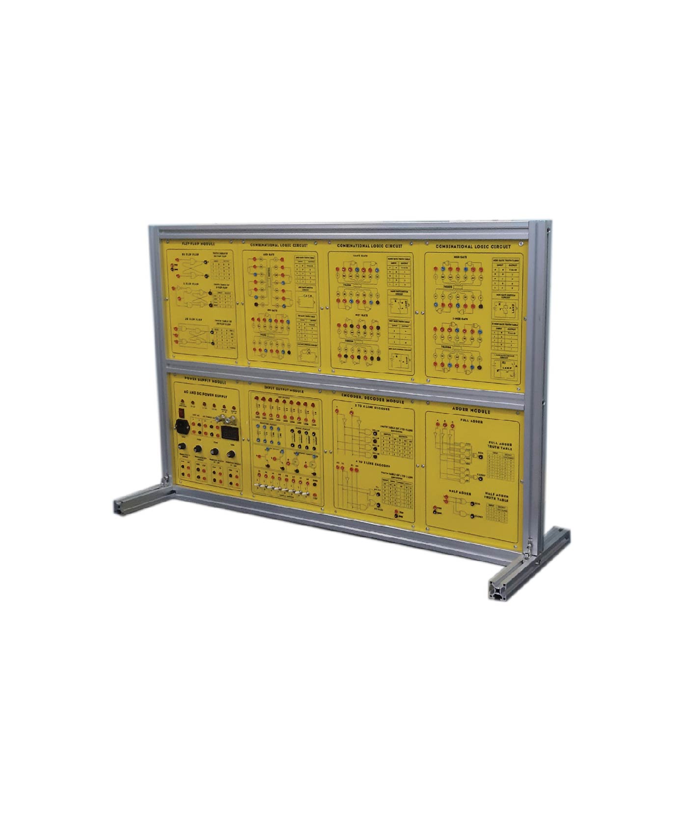
Digital Logic Circuit Trainer
Technical Specification :
1. DC Power Supply
(1) Fixed DC power supply : +5V/2A,
-5V/0.5A, +12V/2A
(2) With overload protection
2. Clock Generator
(1)Signal amplitude output : 3.3V
(2)With adjustable output frequency :
square wave,
1Hz ~ 1MHz, 6 range
(3)Frequency display :4-digit, 7-segment
LED
3. Logic Level Switch : Toggle switches x
8, 3.3V output
4. Data Level Switch : 8-bit DIP switch x
2, 3.3V output
5. Pulse Signal Generator
(1) 2 sets of toggle switch with independent control output
(2) Each set with Q, Q? output
(3) Pulse width > 5ms, each with Denounce
circuit.
6. Logic Level Indicator
(1) 16-bit LED with driver and protection circuit
(2) Input Impedance : > 100K ohms
7. 8 Channel Logic Signal Tracer
(1) 8 logic signal input :input impedance : ≥
100K ohms , 3.3V input
(2) Fixed DC level shift for each channel
(3) Input signal attenuation ratio : 1/8
(4) Output signal : BNC or 2mm plug
(5) Oscilloscope SYNC. select : ALT/CHOP and
scan-frequency adjustment
(6) The function can be used only with analog
oscilloscope
8. 7-segment LED display & frequency measurement 2 DIP switches select the function :
(1) 00 : Scanning display mode
a. Common anode for the control of 7-segments a ~ g.
b. Scanning cathode for the control of
4-digit S0 ~ S3
2) 01 : Independent display mode
a .Input 4-digit of data individually and
decode
the data at 7-segment display separately
b. Independent binary input and hexadecimal output
(3) 10 : Frequency counter for internal
clock
a. Display the frequency of clock generator
from main unit
b. Frequency range : 0.001KHz ~999.9KHz
(4) 11 : Frequency counter for external
clock
a. Display the frequency of clock signal
from external unit
b. Frequency range : 0.001KHz ~ 999.9KHz
9. Rotary Encoder Rotary encoder output :
PA, PB and GND signal, 3.3V output
10. Standard Signal Generator 5 sets of
frequency :
20MHz, 1MHz, 10KHz, 100Hz, 1H
Accessories :
Connecting Wire: 1 set.
Power Cord.
2mm or 4mm safety Jack: 1 set.
User Manual: 1 Set
Others :
Product Origin: China, Taiwan, Japan
Manufacturing: Assemble in Bangladesh
Installation
Training
Warranty: 01 year

