
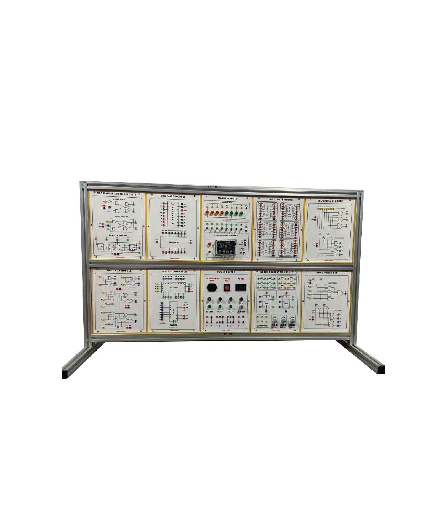
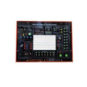
Description
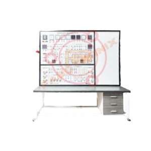
Digital Logic Trainer
List of Experiment:
Module-1: Ohm’s Law: Series, parallel, series-parallel circuit of resistance
Module-2: Kirchhoff’s Law: Kirchhoff’s Law of Voltage; Kirchhoff’s Law of Current
Module-3: Law of Distribution: Law of Voltage Distribution
Module-4: Maximum Power Delivery: Maximum Power Delivery Conditions
Module-5: Thevenin and Norton’s Theorem: Thevenin’s Theorem; Norton’s Theorem
Module-6: Principle of Superposition: Understanding circuit analysis
method when there are two or more current and voltage sources
Module-7: Loop, Node Method: Understanding loop and node equations with independent voltage and current sources
Module-8: RC Series, Parallel Circuit: Understanding Current-Voltage Characteristics of RC Series Circuits: Understanding Current-Voltage Characteristics of RC Parallel Circuits
Module-9: RL Series, Parallel Circuit: Understanding current-voltage characteristics of RL series circuits; Understanding current-voltage characteristics of RL series circuits
Module-10: RLC Series, Parallel Circuit: Understanding RLC Series and Parallel Circuits in AC; Understanding the resonance characteristics of RLC series and parallel circuits
Module-11: Diode: Understanding how diodes work; Understand voltage-current characteristics of diodes; Understanding the Voltage-Current Characteristics of Zener Diodes
Module-12: Clipper, Clamper: Understand the operation of series and parallel clippers and biased clippers; Understanding clamper circuits according to diode direction
Module-13. Rectifier Circuit: Understanding of Half-wave, Full-wave, Bridge Full-wave Rectifier Filter: Understanding circuits of Low Pass and High Pass Filters; Understanding circuits of Band Pass and Band Stop Filters
Hardware Specifications :
Input Parts:
AC Power: 0VAC, 3VAC, 6VAC, 9VAC, 12VAC;
3 digit 7-Segment Display (Selected AC Power)
Variable DC Power-1: +1.5V~+18.5V;
3 digit 7-Segment Display (Output DC Power)
Variable DC Power -2:-1.5V-18.5V; 3 digit 7-Segment Display
(Output DC Power) Analog Signal: +5V–5V
Fixed Power (DC): +20V, +15V, +5V, GND, -5V,-15V
Slide Switch: +15V/0V Switch 2EA; +5V/0V Switch 2EA;
-5V/0V Switch 2EA; -15V/OV Switch 2EA
Button Switch: +15V/0V Switch IEA: +5V/0V Switch IEA: -5V/V
Switch IEA; -15V/0V Switch IEA
Function Generator:
Waveform: Sine/Triangle/Square
DC Offset: -5V~+5V
Amplitude: 0V-10Vp-p
Frequency: 0-1kHz, 1kHz-10kHz, 10kHz-100kHz
Duty Rate: 10-90% (Square)
Output Level: +5V TTL Level
Fixed Frequency: Output Level: +5V TTL, Level;
Frequency: 0.5Hz, 1Hz, 50Hz, 100Hz, 500Hz, 1kHz, 5kliz, 10kHz
Variable Resistor: ΙΚΩ ΙΕΑ. ΣΚΩ ΙΕΑ, 10ΚΩ ΙΕΛ, 50ΚΩ ΙΕΛ
Select Capacitor: 100pF, InF, 10nF, 47nF, 100nF, luf
Select Inductor: 47uH, 100uH, 220uH, 470uH, 1mll, 2.2mH
Output Parts:
LED display: 5pi RED LED SEA
7-Segment Display: Anode Common 7-Segment IEA; Cathode
Common
7-Segment IEA
Speaker: 40 Speaker with Volume Control
Measurement Parts:
Oscilloscope:
Using PC Software (USB Cable connected)
Display: 2.8inch 64K Color TFT LCD, 320×240 Pixels Resolution
Sampling Speed: 250MHz (single ch), 125MHz (dual ch)
Band Width: 70Msps/ch
Measurement Range: -30V~+30V
Voltage Division: 10mV-10V
Record Length: Max 6K samples for single-channel; 3K samples per
dual-channel SEC/DIV Range: 5ns/div-500s/div 1, 2, 5 sequence
DC Gain Accuracy: +-3% for Normal or Average acquisition mode,
10V/div to 10Mv/div
Multi-Tester:
Maximum Resolution: 4000 Counts
AC/DC Voltage: Up to 600V
AC/DC Current: Up to 10A
Resistance: Up to 40ΜΩ
Capacitance: Up to 100Uf
Diode: 0-1V
Testing Modes: Voltage, Current, Resistance, Diode, Capacitance
Measurement Block:
Display: 3 digit 7-Segment display
Measure Select: Voltage/Ampere/Frequency
Voltage measure: 0-30V
Ampere measure: 0~9.99A
Frequency measure: 0Hz-5MHz
Display unit using LED
DAQ:
Using PC Software (USB Cable connected)
Sampling Speed: Ims, 10ms, 100ms Is
Input: 8 bit digital Data
Output: 8 bit TTL Level
Waveform Generator: A/D Convertor with 8 bit output data
Power Protection Circuit:
If the circuit uses more than the allowable current for short-circuit
reasons, shutoff the power
When the temperature inside the equipment is over a certain
temperature (70°C), the power is cut off
LED indicates the location of the power source that is problematic
when Beep sound when power off the power is off
LED informs the status of power connection/operation/short
Power can be switched on/off using a switch
Oscilloscope (1 GS/s sample rate):
Technical Specification:
Min 100 MHz bandwidth, Min 2-channel
Min 1 GS/s sample rate on all channels
20k point record length (Min) on all channels
Min 7-inch WVGA color display with 15 horizontal divisions
At least 32 automated measurements
Vertical resolution: At least 8 bits
Maximum Input Voltage: 300 VRMS
Bandwidth limit: Min 20 MHz (Typ)
Input coupling: DC, AC
Input impedance: 1 M2 ±2% in parallel with 14 pF +2 pF or better
Vertical zoom: Vertically expand or compress a live or stopped waveform
Average: From 2 to 256 waveforms included in average.
Timebase accuracy: ±25 x 10-6 over any >1 ms interval
Timebase range: 2 ns/div to 100 sec/div in a 1-2-4 sequence
Horizontal zoom: Horizontally expand or compress a live or stopped waveform
Deskew range: ± 100 nsec
Trigger modes: Auto, Normal, Single Sequence
Trigger source: CHI, CH2, AUX IN, AC Line
Trigger Coupling: DC, Noise Reject, High Frequency Reject, Low
Frequency Reject
At least following Measurements should include: Period, Frequency,
Rise Time, Fall Time, Positive Duty Cycle, Negative Duty Cycle, Positive
Pulse Width, Negative Pulse Width, Burst Width, Phase, Positive
Overshoot, Negative Overshoot, Peak to Peak, Amplitude, High,
Low, Max, Min, Mean, Cycle Mean, RMS, Cycle RMS, Positive
Pulse Count, Negative Pulse Count, Rising Edge Count, Falling
Edge Count, Area, Cycle Area, Delay FR, Delay FF, Delay FR, and Delay RR.
Accessories:
Single-phase power cord
4mm Banana Socket-1Set
User Manual
Others:
Brand: FaboTronix
Country of Origin: China, taiwan, japan.
Manufacturing: Assemble in Bangladesh
Training
Reviews
There are no reviews yet.