Description
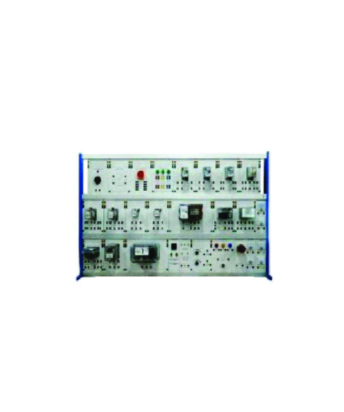
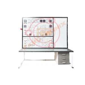
Electrical Power Protection trainer
Features :
Protection Relay Experiment Trainer:
Experiment projects are complete, experiment content is rich,
design is reasonable, which are beneficial to broaden the
students’ knowledge Experimental device has excellent compatibility
and scalability.
Experimental installations adopt platform design, laboratory
modules using component design Experimental device has
strong intuitionist.
Each relays is the abdomen – installed on the panel surface,
students can clearly see the action of every relay, and are
convenient to set relay values.
At the same time, the relays and other components electrical
diagrams of are painting on each panel, which are complete
and consistent teaching materials, can help students under-
stand the book knowledge, improve the experimental results.
The experiments are strong package, the AC-DC power
supply, instrumentation, relay and experimental connecting
wire in experiment all fully equipped Experiment has
authenticity.
The relays used in experiment are relays which are currently
using on-site power system, and better reflect the status of the
power system, and lay a good foundation to engage in design,
installation, debugging, maintenance and other work to for
students after graduation for protection system Structure is
reasonable.
The whole structure adopt a three-tier structure, panel ranking
according to the actual line with the flow, experimental
function block is clarity, carefully designing improve experimenter’s
understanding of the system, wiring facilitate and the
efficiency of the experiment.
The experiment device has perfect protection measures.
The device provide leakage circuit breakers and other physical
security protection measures. Various instruments and
power supplies all have a perfect protection function.
Experiment Project :
Relay Specialty:
Current relay specialty experiment
Voltage relay specialty experiment
Electromagnetic time relay experiment
Intermediate relay specialty experiment
Signal relay specialty experiment
Transistors negative sequence voltage relay
experiment
Impact relay specialty experiment
Flashlight Relay specialty experiment
Three-phase reclosing device experiment
Rectifier direction characteristic impedance
Relay experiment.
Differential relay experiment.
Power direction relay experiment
Anti-time over current relays characteristics
experiment
Line Protection:
Over-current protection circuit experiment
Low voltage start over-current protection and
overload protection experiment.
Repeat action of manual revert to central signal
device experimental.
Technical Specifications of Modules:
Signal Relay:
Voltage: 220VDC
NO Contact: 2 sets
Adjustable Single Phase:
Voltage: 0 ~ 240VAC
Current: 1A
Bridge Rectifier:
Voltage: 1000V
Current: 35A
Universal Change Over Switch:
Rated Current: 20A
NO Contacts: 4 sets
Simulate Switch Board:
Rated voltage: 240VAC
Push Button X 3 units
Current Relay:
Current: 1.25A to 5A
NO Contact: 1 set
Negative Sequence Relay:
Input Voltage: L1, L2 & L3
Voltage: 220VDC
Time Delay Contractor:
Coil Voltage: 240VAC
Contact: NO & NC
Time: 0…60seconds
Intermediate Relay:
Voltage: 220VDC
Trigger Current: 1A
NO Contact: 2 sets
NC Contact: 2 sets
Phase Analyzer:
Input: L1, L2 & L3
To check phase voltage in
correct/incorrect sequence
Adjustable Three Phase:
Protection Fuse 2A x 3 units
Pilot Lamps L1 , L2 & L3
Fault Current Circuit Breaker 3 Poles
Output: 0…240VAC x 3 units;
0…415VAC
Input: AC 415V, 50Hz 3-Phase
Timer Relay:
Voltage: 220VDC
Time: 0.1s to 1.5s
NO Contact: 2 sets
NC Contact: 2 sets
Low Voltage Relay:
NO Contact: 1 set
NC Contact: 1 set
Impulse Relay:
Voltage: 220VDC
Current: 0.16A
NO Contact: 1 set,
NC Contact: 1 set
Synchronous Detector,
Voltage: 220VDC
Voltage: Compare: 110VAC
NO Contact: 1 set
NC Contact: 1 set
Flashing Relay:
Voltage: 220VDC
NO Contac: 2 sets
Overload Relay:
Current: 8A to 16A
NO Contact: 2 sets
Electronic Timer:
Start, stop and reset function
Contactor:
Voltage: 220VDC
NO Contact: 2 sets
NC Contact: 2 sets
Rheostat 100Ω/1kΩ:
Rheostat 1kΩ/100W
Rheostat 100Ω/100W
Indicator and Buzzer:
Lamp Voltage: 240VAC
Buzzer Voltage: 240VAC
Alarm Indicator:
Voltage: 240VAC
AC Voltmeter:
Range: 300V & 500V
AC Ammeter:
Range: 5A & 20A
DC Current & Voltmeter
Voltage Range: 300V
Current Range: 10A
Three Phase Bridge Rectifier:
Three phase rectifier bridge
Maximum Voltage: 400VAC
Maximum current: 10A
Fault Current Circuit Breaker:
Protection Fuse 2A x 3 units
Pilot Lamps L1 , L2 & L3
Fault Current Circuit Breaker
Resistive Load:
Compose of three resistances with
possibility to connect in star/delta or
parallel, controlled by three switches
with 7 steps variable per phase.
Max Power: 1200 watt
Voltage: 380/220 Volt (Star/Delta)
U-LINK: For connecting junction point
Safety Connecting Lead: 4mm
connecting leads
Vertical Frame:
High level: DIN standard A4 with two
shelves
Material: Aluminium
Side Frame: T shape
Size: 3-Layer 1450mm Length
Accessories :
Standard accessories.
User manual: 1 Nos.
Connecting Wire: 1 set
Others :
Origin Parts : China, Taiwan, Japan.
Manufacturing in Bangladesh.
Warranty: 01 year.
Installation, Testing.
Training.

