
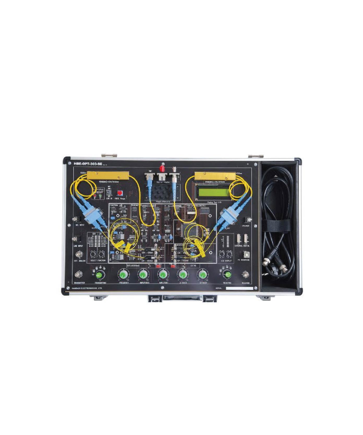
Description
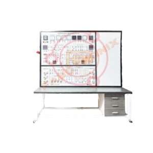
Optical Network System Trainer
Features
The system conduct the WDM transmitting & receiving test, based on such
built-in functions as Function Generator, Dual Light Source (1310/1550nm),
Dual Optical Receiver (power meter), and Digital Oscilloscope.
The system conduct optical communication practice and operation test by use
of a light source with various wavelengths. (650nm-MM, 1310nm-SM, 1550nm-SM, etc.)
It possible to make a test on physical properties of light-using equipment. (e.g.
total reflection principle, refraction & reflection property, loss property etc.)
The system measure Optical Coupler, Attenuator (SdB, 10dB), WDM (Mux & Demux).
Is also offer performance tests on different kinds of optical application devices provided.
Digital control of all input/output data by use of FPGA. (e.g., LCD control, Signal Input/Output Selection, etc.)
It control PC software through private digital devices (Digital Potentiometer,
8-channel, 12-bit Serial DAC, etc.) and programs: Selection Function, LCD
Display, Amplitude, Frequency, LD Bias Current, etc.
It inputs various user-designating data signals beside outputting built-in
functions (i.e., selection of eight signals – Sign, Triangle, Square, Ext Dig, Ext Anal.
The system use private 8-channel, 12-bit ADC (Analog Digital Converter) to
improve the accuracy of LCD output data in the equipment.
The system should use private high-speed/high-dynamic range ADC for
parallel transmission of input/output data. (12-bit, 1-channel, 20MSPS, High SNR-69dB, etc.)
The system can make a PC output of every output waveform in equipment It has a built-in digital oscilloscope function
Technical Specification :
Light Source:
FP-LD (1310, 1550nm) – Singlemode wavelength
MQW-FP Laser diode module
Wavelength: 1310/1550nm
Built in optical isolator
Built in InGaAs monitor PIN photodiode
10/125um(Core/Clade) single-mode fiber pigtail with
SC-PC connector
Optical output power: 10mW (max)
FP-LD (650nm) -Multimode wavelength
650nm wavelength (Visual LD)
Light output power is more than-6dBm
Uncooled operation without TEC
Optical Detector:
InGaAs PIN PD-SM @ 1310/1550nm wavelength
Operation @ 1000~1600nm
Low dark current(0.1nA)
Low capacitance
High responsiveness (0.9 A/W)
InGaAs PIN PD-MM @ 650nm wavelength
Diode: Si, Ge
Digital Control:
FPGA: EP2C5Q208(ALTERA)
SRAM: 256K 16 15ns
Low Speed ADC: 8ch 12bit 200Kbps ADC
High Speed ADC: Ich 12bit 20Mbps ADC
Scrial DAC: 8ch 12bit 15 DAC
Signal Input:
INTERNAL
Function generator Frequency range: 10Hz-50KHz,
Amplitude: OV-5Vpp
Wave type: Sin, Triangle, Square, User Digital, User Analog
EXTERNAL: OV-5Vpp Analog & Digital port,
MIC input
Signal Output Terminal: BNC, Audio Jack
Power Supply:
Input: 85-264Vac 50/60Hz
Output: 5Vdc (3/0.3A), +12Vdc (0.7A), +3.3Vdc, +2.5Vdc
Optical devices provided:
Basic devices provided
Visual Attenuator, Fixed Attenuator (5dB/10dB)
WDM Set (MUX, DEMUX-1310/1550nm)
Hybrid Adapter Set, Optical Coupler, Single Mode Fiber
650nm Visual LD & PD, Multi mode Fiber, Multi mode Coupler
Optical Apparatus set Ete, USB Dongle
Main Screen of Program:
The system program is the software for observing a phenomenon
occurred from the main board, and output characteristics are as follows:
Optical power (dBm) display resulting from PDO (1310nm) and PD1
(1550nm) through the Mini LCD window (the function of optical
power meter)
References of optical power meter
Display of optical power value of monitor LD detected from Monitor
PD
Display of output data from light source (1310/1550nm)
Display of PDO and PD1 output waveforms (1310/1550nm)
X-Y output of input-output waveform
The FFT of each input/output waveform (the function of spectrum
analyzer)
Saving all measured data(Text/BMP)
The measurement mode by section. It samples every section of output
waveform, making a comparison and analysis of them
Data analysis in the form of becoming real-time processing by
receiving and making a continuous arrangement
User Signal Choices:
1. Test of transmission of single light source (1310nm or 1550nm)
CHI: LD0(1310nm)/PD1
CH2: LD1(1550nm)/PDO
2. Test of transmission of dual light source
CHI: LD0(1310nm)/PDI
CH2: LD1(1550nm)/PDO
3. Measurement of the features of Si Diode
CH1-Si_In
CH2-Si Out
4. Measurement of the features of Ge Diode
CHI-Ge In
CH2-Ge Out
5. MINI LCD
This mini LCD shows the functions of optical power meter. Data
output is calculated by converting the power value of light source
and reference value of variations to dBm and dB. LCD Display
Output
LDOLDIM-PDO M-PDI SiGe
PDO
PDI
Accessories:
Single-phase power cord
4mm Banana Socket-1Set
User Manual
Others:
Brand: FaboTronix
Country of Origin: China, taiwan, japan.
Manufacturing: Assemble in Bangladesh
Training
Reviews
There are no reviews yet.