Description
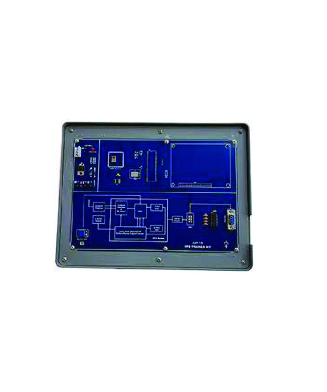
Telecommunication Trainer
Experiment Content :
Setting up an oscilloscope
Introduction to the Telecoms-Trainer
Modelling equations
Amplitude Modulation (AM)
Double Sideband (DSB) modulation
Amplitude (AM) demodulation
Double Sideband (DSB) demodulation
Single Sideband (SSB) modulation & demodulation
FM modulation
FM demodulation
Sampling & reconstruction
PCM encoding
PCM decoding
BW limiting and restoring digital signals
Amplitude Shift Keying (ASK)
Frequency Shift Keying (FSK)
Binary Phase Shift Keying (BPSK)
Quadrature Phase Shift Keying (QPSK)
Spread Spectrum – DSSS modulation & demodulation
Under sampling in Software Defined Radio
Technical Specification :
Adder
Adder 1:
Dual input variable gain from 0 to 2 (inverting)
Bandwidth approx. 600kHz
Adder 2:
Dual input fixed gain of 1
Bandwidth approx. 600kHz
Amplifier
Bandwidth DC to approx. 600kHz
Gain 0.2 to 10
Channel Module
CHANNEL BPF Fcenter = 100kHz
Pass band = 24kHz (from 88 kHz & 112 kHz)
Stop band = 140kHz, -35dB (approximately at 30kHz &
170kHz)
Gain = 1
Type: 6th order Chebychev with 0.1dB ripple
BASEBAND LPF
Fcutoff = 1.6 kHz
Gain = 0.9
Type: 4th order Butterworth
Divider
Digital Logic Level Input & Output Signals 0 to 5V
Division Factors -1, /2, /4, /8 (switch selectable by user)
Bandwidth approx. 1MHz
Dual Analog Switch & Sample/Hold
Analog Input Bandwidth 50kHz maximum
CONTROL clock 100kHz
CONTROL Input Levels: digital-level only, 0V and 5V
Maximum Analog Input Level: 4Vpkpk
Accessories :
Standard accessories.
User manual: 1 Nos.
Connecting Wire: 1 set
Others :
Origin Parts : China, Taiwan, Japan.
Manufacturing in Bangladesh.
Warranty: 01 year.
Installation, Testing.
Training.