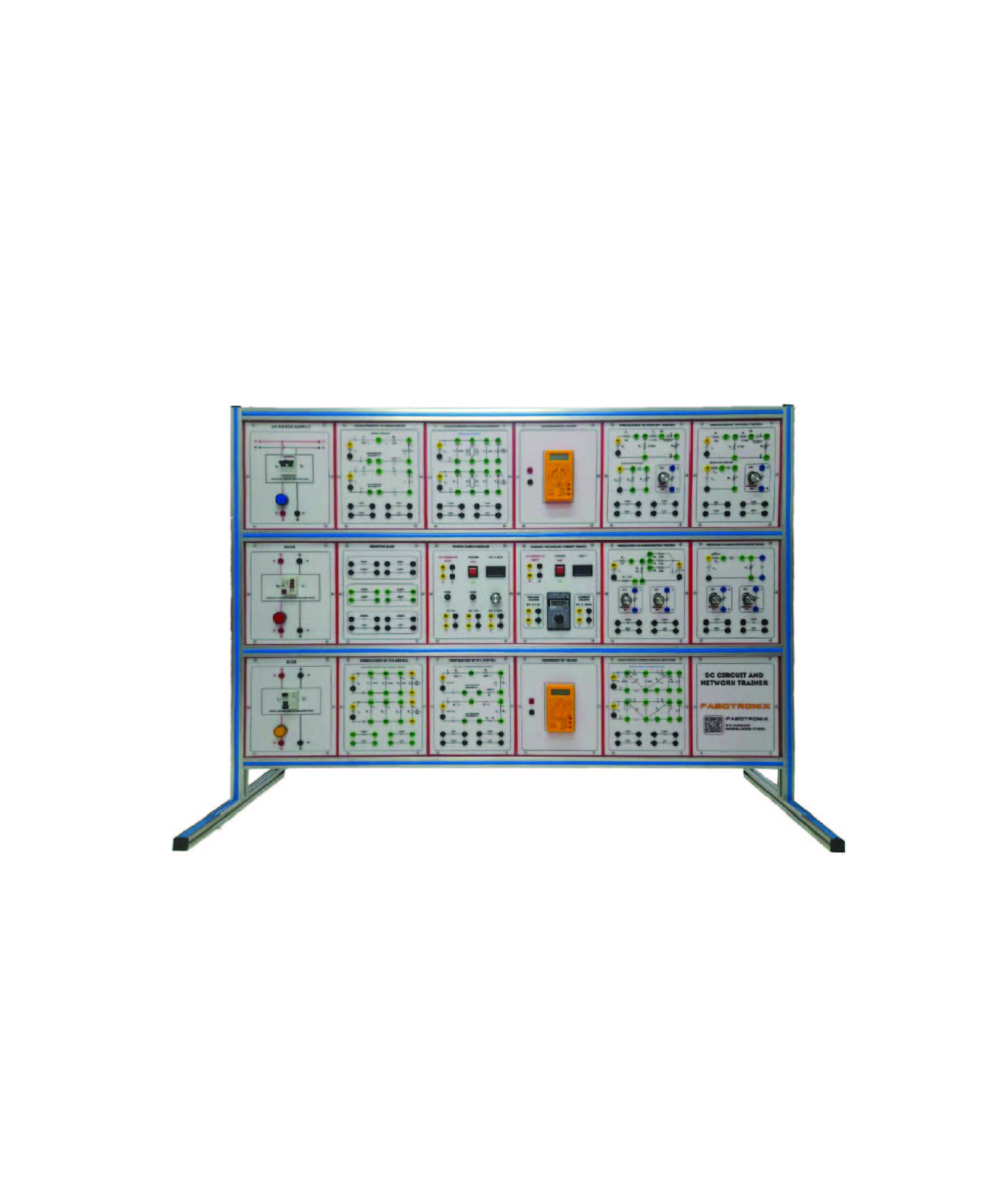
Description
Verification Of Kirchhoff’s Law Of Voltage And Current/ Verification Of Maximum Power Transfer Theorem (Digital)/ Verification Of
Superposition Theorem (Digital)/ Verification of Thevenin’s & Norton’s Theorem (DC Circuit & Network Trainer)
List of Experiment:
Module-1: Ohm’s Law: Series, parallel, series-parallel circuit
of resistance,
Module-2: Kirchhoff’s Law: Kirchhoff’s Law of Voltage;
Kirchhoff’s Law of Current
Module-3: Law of Distribution: Law of Voltage Distribution
Module-4: Maximum Power Delivery: Maximum Power
Delivery Conditions
Module-5: Thevenin and Norton’s Theorem: Thevenin’s
Theorem; Norton’s Theorem
Module-6: Principle of Superposition: Understanding circuit
analysis method when there are two or more current and
voltage sources
Module-7: Loop, Node Method: Understanding loop and
node equations with independent voltage and current
sources
Module-8: RC Series, Parallel Circuit: Understanding
Current-Voltage Characteristics of RC Series Circuits:
Understanding Current-Voltage Characteristics of RC Parallel Circuits
RC Series Circuits: Understanding Current-Voltage
Characteristics of RC Parallel Circuits
Module-9: RL Series, Parallel Circuit: Understanding
current-voltage characteristics of RL series circuits;
Understanding current-voltage characteristics of RL
series circuits
Module-10: RLC Series, Parallel Circuit: Understanding
RLC Series and Parallel Circuits in AC; Understanding
the resonance characteristics of RLC series and parallel circuits
Module-11: Diode: Understanding how diodes work;
Understand voltage-current characteristics of diodes;
Understanding the Voltage-Current Characteristics of
Zener Diodes
Module-12: Clipper, Clamper: Understand the operation of
series and parallel clippers and biased
clippers; Understanding clamper circuits according to
diode direction
Module-13. Rectifier Circuit: Understanding of
Half-wave, Full-wave, Bridge Full-wave Rectifier
Filter: Understanding circuits of Low Pass and High
Pass Filters; Understanding circuits of Band Pass and
Band Stop Filters
Hardware Specification:
Input Parts:
AC Power: 0VAC, 3VAC, 6VAC, 9VAC, 12VAC; 3 digit 7-Segment Display (Selected AC Power)
Variable DC Power- 1: +1.5V ~ +18.5V; 3 digit 7-Segment Display (Output DC Power)
Variable DC Power -2: -1.5V ~ -18.5V; 3 digit 7-Segment Display (Output DC Power)
Analog Signal: +5V ~ -5V
Fixed Power (DC): +20V, +15V, +5V, GND, -5V, -15V Slide Switch: +15V/0V Switch 2EA; +5V/0V Switch 2EA; -5V/0V Switch 2EA; -15V/0V Switch 2EA
Button Switch: +15V/0V Switch 1EA; +5V/0V Switch 1EA; -5V/0V Switch 1EA; 15V/0V Switch 1EA
Function Generator:
Waveform: Sine/Triangle/Square
DC Offset: -5V~+5V
Amplitude: 0V~10Vp-p
Frequency: 0 ~ 1kHz, 1kHz ~ 10kHz, 10kHz ~ 100kHz
Duty Rate: 10~90% (Square)
Output Level: +5V TTL Level
Fixed Frequency: Output Level: +5V TTL Level; Frequency:
0.5Hz, 1Hz, 50Hz, 100Hz,
500Hz, 1kHz, 5kHz, 10kHz
Variable Resistor: 1kΩ 1EA, 5kΩ 1EA, 10kΩ 1EA, 50kΩ 1EA
Select Capacitor: 100pF, 1nF, 10nF, 47nF, 100nF, 1uF
Select Inductor: 47uH, 100uH, 220uH, 470uH, 1mH, 2.2mH
Output Parts:
LED display: 5pi RED LED 8EA
7-Segment Display: Anode Common 7-Segment 1EA;
Cathode Common 7-Segment 1EA
Speaker: 4Ω Speaker with Volume Control
Speaker: 4Ω Speaker with Volume Control
Measurement Parts:
Oscilloscope:
Using PC Software (USB Cable connected)
Display: 2.8inch 64K Color TFT LCD, 320×240 Pixels
Resolution
Sampling Speed: 250MHz (single ch),125MHz (dual ch)
Band Width: 70Msps/ch
Measurement Range: -30V~+30V
Voltage Division: 10mV~10V
Record Length: Max 6K samples for single-channel; 3K
samples per dual-channel
SEC/DIV Range: 5ns/div~500s/div 1, 2, 5 sequence
DC Gain Accuracy: +-3% for Normal or Average acquisition
mode, 10V/div to 10Mv/div
Multi-Tester:
Maximum Resolution: 4000 Counts
AC/DC Voltage: Up to 600V
AC/DC Current: Up to 10A
Resistance: Up to 40MΩ
Capacitance: Up to 100Uf
Diode: 0~1V
Testing Modes: Voltage, Current, Resistance,
Diode, Capacitance
Measurement Block:
Display: 3 digit 7-Segment display
Measure Select: Voltage/Ampere/Frequency
Voltage measure: 0~30V
Ampere measure: 0~9.99A
Frequency measure: 0Hz~5MHz
Display unit using LED
DAQ:
Using PC Software (USB Cable connected)
Sampling Speed: 1ms, 10ms, 100ms 1s
Input: 8-bit digital Data
Output: 8-bit TTL Level
Waveform Generator: A/D Convertor with 8-bit output
data
Power Protection Circuit:
If the circuit uses more than the allowable current
for short-circuit reasons, shutoff the power
When the temperature inside the equipment is over a
certain temperature (70 ), the power is cut off
Beep sound when power off
LED indicates the location of the power source that is
problematic when the power is off
LED informs the status of power connection/
operation/short Power can be switched on/off using a switch
Accessories :
Standard accessories.
User manual: 1 Nos.
Connecting Wire: 1 set
Others :
Origin Parts : China, Taiwan, Japan.
Manufacturing in Bangladesh.
Warranty: 01 year.
Installation, Testing.
Training.