
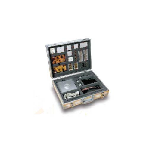
Description
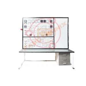
Micro wave Communication Trainer
Technical Specification :
Power Supply :
• Power Supply is a state-of-the-art solid-state regulated power
supply for operating low power Klystrons. It incorporates a
number of proprietary. Regulated Beam Supply and Repeller
Supply voltages. LED Digital meter for Beam voltage current
and Repeller voltage. Compact and Reliable. Modular construction
for easy maintenance. In addition to AM and FM modulation
of beam current a provision for external modulation is provided.
Beam Supply
• Voltage: Variable 240 – 420 VDC
• Current: 50 mA
• Ripple: < 4 m Vrms (ON Load) Repeller Supply
• Variable: -18 V to -270 V DC (ON Load) Filament Supply
• Adjustable: 6.3 VDC
• Over-Load trip current: 65 mA
Digital Panel Meter
• 2 V Modulation: AM (Square)
• Frequency Range: 500 – 2000 Hz 0 – 110
• Display: 16 × 2 Characters LCD
• Sensitivity: 0.1 mV for 200 W input impedance
• Noise Level: Less than 0.02 mV
• Range: 0 – 60 dB in 10 dB steps
• Input: Un-biased low and high impedance biased crystal
(200 W and 200 K)
• Display Select: SWR 1 – 9 dB 0 10
• Modes: Normal Audio PC-Interface
• Gain Control: Adjusts the reference level variable range 0
-10 dB approx.
• Input Connector: BNC (F)
• Input Frequency: 1000 Hz ± 10%
• Power Supply: 220 V ± 10% 50Hz
Solid Directional Cell
• These are used to measure dielectric constant of any solid
material these consists of a cavity for keeping the sample and
micrometer to read the position of sample.
• Frequency: 8.2 – 12.4 GHz
• Max. length of cell: 100 mm
• Plunger movement: 25 mm
Cross Directional Coupler
• Cross Directional Coupler consists of two waveguide
sectional joint at (90°) with the coupling element mounted
into the common broad wall.
• Coupling (dB): 20 dB
• Coupling accuracy: ±1 dB
E-Plane Tee
• Frequency: 8.2 – 12.4 GHz
• Max. length of cell: 200 mm
• Plunger movement: 65 mm
Micrometer Type Frequency Meter
• Micrometer type frequency meters are consisting of a
microwave cavity with plunger and a section of waveguide.
It consists of a micrometer to measure its position
for measuring frequency.
• Frequency: 8.2 – 12.4 GHz
• Max. VSWR: 1.15
• Calibration accuracy: ±2%
• Calibration increment: 10 MHz
Waveguide Antennas
• Frequency: 8.2 – 12.4 GHz
• Antenna type: Pyramidical
• Gain: 16
Multi-hole Directional Coupler
• Directional coupler is designed to measure incident
and reflected power values long scale length and
numbered calibration marks provide high. resolution
which is particularly useful when measuring frequency
difference of small frequency change. Each adaptor
covers the 50% of the waveguide.
• Frequency: 8.2 – 12.4 GHz
• Connector: N Type
• Max. VSWR: 1.12 at 10.5 GHz
• Return loss: -24.5 at 10.5 GHz
Tunable Probe
• Tunable probes are very useful devices to measure the
SWR and Impedances. Tunable probe is consisting of a
crystal detector and a small wire antenna in coaxial
housing. Its depth of penetration into the slotted section
is variable.
• Frequency: 8.2 – 12.4 GHz
• Detector: IN23
• Tunable type
Klystron Mount
• Klystron mounts are used to transmit microwave
Accessories:
Single-phase power cord
4mm Banana Socket-1Set
User Manual
Others:
Brand: FaboTronix
Country of Origin: China, taiwan, japan.
Manufacturing: Assemble in Bangladesh
Training
Reviews
There are no reviews yet.