Description
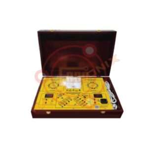
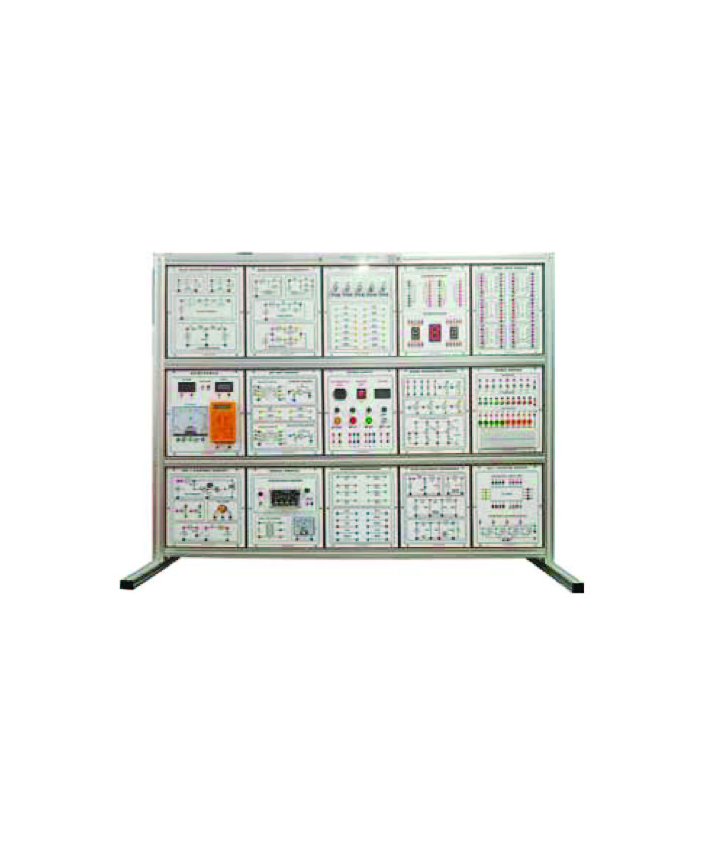
Basic Electronics Circuit Trainer
Technical Specification :
Module One: Basic Electronic Circuits
Diode and Transistor Switches
Basic applications of Operation Amplifiers (I)
– Inverter OP Amplifier fin 1 kHz and Vin 2 VPP
– Inverter fin 1 kHz and Vin 2 VPP
– Non-Inverter OP Amplifier fin 1 kHz and Vin 2 VPP
– Voltage Follower fin 1 kHz and Vin 2 VPP
Basic Applications of Operation Amplifiers (II)
– Comparator Vs ±12 V, V ref ±1 V
– Zero Crossing Detector Vs ±12 V, V ref 0 V
– Photoelectric Controller Vs ±12 V, V ref 6 V
Module Two: Waveform Generator Circuits –
Schmitt Trigger Circuit
– Schmitt Trigger Vs ±12 V, fin 1 kHz, Vin 10 VPP
– 555 Delay Circuit Vs 12 V, Ton 6 secs
– Delay Turn off Circuit VCC 12 V, Ton 4 ~ 9 secs
As table Multi vibrator
– OPA As table Multi vibrator Vs ±12 V, V out 22 VPP Square wave
– 555 As table Multi vibrator VCC 12 V, V out 11 VPP Square wave
– Sparkling Lamp
Crystal Oscillator
– TTL Crystal Oscillator fo 100 kHz ~ 4 MHz
– OPA Crystal Oscillator fo 1 MHz, V out 6 VPP
Module Three: Digital Circuits
BCD Adder: IC 4560B
BCD Subtractor: IC 4560B, 4561B
Applications of Timer
– Monostable Circuit V cc 12 V, Ton 5 ~ 10 seconds
– Touch Switch V cc 12 V, Ton 5 secs
– Alarm Circuit V cc 5 V, IC 555, Speaker
Digital Display Circuit
– 4518 Counter
– Digit Display Circuit V cc 5 V, IC CD4518
Application of LCD
– LCDM Circuit V cc 5 V, IC: 4511
Module Four: Signal Process Circuits –
Digital to Analog Converter
– R 2R Ladder Network Circuit V cc 8 V, V out= 0 ~ 7.5 V
– D/A Converter Vs ±15 V, IC DAC0800
Analog to Digital Converter
– A/D Converter V cc 5 V, IC ADC0804
Filters: Low, High, Bandpass and B and stop Filter
Module Five: Regulated DC Power Supply –
Applications of 7800 Series Regulator
– 7805 Regulator Characteristic Vin 8 ~ 15 V, V out 5 V
– 7805 Expanded Voltage Vin 12 V, V out 5 ~ 7 V
– 7805 Variable Regulator Vin 12 V, V out 11 V
– 7805 Current Source RL 0 ~ 330Ω, I out 10 mA
Applications of 7900 Series Regulator
– 7905 Regulator Characteristic Vin 8 ~ 15 V, V out -5 V
– 7905 Expanded Voltage Vin -12 V, V out -5 ~ -7 V
– 7905 Variable Regulator Vin -12 V, V out -11 V
– 7905 Current Source RL 0 ~ 330Ω, I out 11 mA
Module Six: LED and Transistor Application Circuits –
Electronics competition-answer machine
Remote lamp controller
Electronic wheel amusement machine
Function Generator and DC Power Supply:
Waveforms: Sine, Triangle, Square and TTL Pulse
Amplitude: >10Vpp
Impedance: 50Ω ±10 %
Duty Control: 30 % to 60%
Display: 6 Digit LED
Frequency Range: 10Hz to 100 kHz (4 Ranges)
Frequency Range: 100Hz to 1 MHz (4 Ranges)
Constant Voltage Output: ± 5V, ±12V
Variable Voltage Output: 0 V to ±15V
Power source 220 to 230V AC, 50Hz, 1 Phase
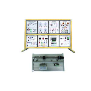
Supplied with below Circuit Principle Trainer as standard for
experiments in teaching courses such as
‘Electrotechnics’ and ‘Circuit principle’ –
Features:
This trainer composed of aluminum alloy box, power supply,
common signal source, measuring meter, experiment circuit
modules, etc.
Most of the components install on the reverse side of circuit board
and the front should be painted with schematic circuit diagram,
which is convenient for student to understand
Multiple power sources provided, including DC voltage stabilized
power supply, constant current and constant voltage source, etc.
It should be suitable for experiment teaching courses such as
‘Electrotechnics’ and ‘Circuit principle’.
Training Content:
Basic electrotechnical instrument usage, calculation of measuring error
Method to reduce instrument measuring error
Resistor parallel connection and series connection circuit
Resistor parallel-series connection circuit
Troubleshooting of DC resistor circuit
Voltage current characteristic mapping of linear circuit and nonlinear circuit element
Potential, voltage measurement and circuit potential diagram drawing
Kirchhoff’s law verification and its failure diagnosis
Superposition theorem verification and its failure diagnosis
Equivalent transformation of voltage source and current source
Thevenin and Norton Theorem verification
Two-port network test
Reciprocal theory experiment
Maximum power transmission condition measurement
First order circuit response test
Second order dynamic circuit response research
R, L, C element impedance characteristic measurement
RC serial-parallel frequency selective network characteristic test
R, L, C series resonant circuit research
Gyrator experiment
Controlled source (VCCS, VCVS, CCVS, CCCS) experiment research
Technical Specifications:
Power supply:
– Input AC: 220V±10%, power consumption 0.5KVA
– Output DC stabilized voltage: ±12V/1.5A; 5V/1.5A
– Output adjustable DC st abilized voltage: DC 0V … ±24V/1A
continuously adjustable, with short-circuit protection and self-re-
covery function
– Constant current source: 0 … 50mA adjustable constant current
source, with open circuit protection
– Safety protection: Dedicated power input and output protection
circuit board, with earth protection, leakage and overload protection,
error operation protection, etc.
Measuring instrument:
– DC ammeter: 1mA
– DC ammeter: 50mA
– DC voltmeter: 3V
– DC voltmeter: 30V
Function generator:
– Output waveform: Square wave / triangular wave / sine wave
– Amplitude: Sine wave 0 … 10V (peak-to-peak value 10V, symmetric
negative & positive); triangular wave 0…14V (peak-to-peak
value 14V, symmetric negative & positive); square wave 0…14V
(peak-to-peak value 14V, symmetric negative & positive)
– Frequency range: Four-stage, (10Hz…100Hz) / (100Hz…1KHz) /
(1KHz…10KHz) / (10KHz…100KHz)
Experiment modules:
– Components voltage current characteristic research
– Circuit potential research
– Thevenin theorem and Norton theorem
– Superposition theorem and reciprocal theory
– Verification of Kirchhoff’s law
– Capacitance charge-discharge research
– Passive two-port network
– First order dynamic circuit
– Second order dynamic circuit
– AC parameter measurement
Series, parallel resonant circuit
– Controlled source VCVZ, VCCS circuit
– Gyrator circuit
Accessories: Power cord, Set of connection cables 2mm, Guide
book and Digital multimeter
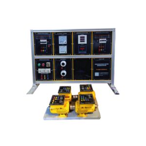
Supplied with below H2 Fuel Cell Kit as standard for demonstration
in Renewable Energy range.
Features:
Understanding the physical basics of electrolysis and fuel cell
Together with PEM-fuel cell and the components of a complete
solar-hydrogen cycle (electrolyzer, PEM fuel cell and solar module),
this product should represent the most comprehensive fuel cell
experimentation system
The electrical consumer (motor) should allow for realistic and
demonstrative experiments
Subjects of Learning:
Set up of an electrolyzer and fuel cell
Characteristics and Operation of an electrolyzer
Characteristics and Operation of a PEM-Fuel cell
Faraday and energy efficiency of the electrolyzer and PEM-fuel cell
Technical Specifications:
PEM-Fuel Cell Module: High performance PEM fuel cell to convert
hydrogen and oxygen into electricity and water
Electrolyzer module and Kit box
Potentiometer module:
– Plug-in module with adjustable resistance
– Resistance continuously adjustable: 0 – 1.1kΩ
– Maximum current: 200mA
– Module contain two potentiometers connected in series (1 x 100Ω
and 1 x 1 kΩ)
– Allow an exact adjustment of the resistance while having a large
resistance range
– Layout: Plug-in module with 4mm jacks
– Grid-dimension of the jacks: 70mm
– Module size: 85mm x 85mm
Motor Module without Gear:
– Plug-in module with DC-motor
– Initial current: 20 mA
– Initial voltage: 0.35 V
– Equipped with automatic fuse protecting from overvoltage
– Layout: Plug-in module with 4 mm jacks
– Grid-dimension of the jacks: 70mm
– Module size: 85mm x 85mm
Solar module:
– Solar module with minimum 5 high efficiency polycrystalline
solar cells
– 2.5 V or higher open circuit voltage
– 420 mA or higher short circuit current
– 1 Wp peak power
– Optimized low light behavior
– Solar cell size 5 pcs. 26 mm x 52 mm
– Contacting via 4mm jacks
– With connecting 4mm banana plugs the module can be set up
with an angle of ca. 80°
– Grid-dimension of the jacks: 70 mm
– Module size: 85 mm x 151 mm
Gas storage module and Propeller
Base unit Large:
– Main board for the plug-in system with 3 slots
– Grid-dimension of the plugs: 70 mm
– Enable series and parallel connection of the modules
– Changing between series and parallel connection by turning the
modules
– Equipped with 4 additional 4 mm jacks for connecting measuring
lines
Lamp with table clamp: Optimal for providing lighting for the
solar panels during indoor experiments
Power module:
– The Power Module should be a compact, robust and easy-to-use
power supply for experiments
– The voltage to be varied incrementally in 0.5V steps from 0 to 12V
– It supply up to 24W output power
– Output voltage: 0 – 12V DC
– Maximum current: 2A
– Maximum output power: 24W
– Automatic overcurrent detection
– Voltage variation in 0.5V steps (manually)
– Accuracy: ±0.15V
– Contacts: 4mm standard connectors and compatible to main board
– Input voltage: 110 – 230V AC, 50Hz
– Adaptors for all common sockets included
Lid for tray and Insert
Info sheet initial startup and Layout diagram
25 cm Test leads (black and Red) x 2 of Each color
Printed Instructions Manual should be supplied
Accessories:
Single-phase power cord
4mm Banana Socket-1Set
User Manual
Others:
Brand: FaboTronix
Country of Origin: China, taiwan, japan.
Manufacturing: Assemble in Bangladesh
Training